
RCR40 Manual: Chassis
The first step in the build process is to fully disassemble the chassis.
Carefully remove all components paying particular attention to how and in what order items come apart. It is a good idea to photo document each sub-assembly "in detail" prior to disassembling. This will help you immensely during re-assembly. Photograph each joint, re-install bolts into rod ends, tag and label parts, etc. You will be grateful you did later.
To remove the rack and pinion, pull back the passenger side inboard boot from the rack and unscrew the inner tie rod. With the tie rod separated from the rack, pull the outer tie rod as far outboard as possible. This will provide the necessary room to pull the passenger side of the rack assembly back (rearward) and then swing the assembly out.

With chassis stripped you are ready to start your "build". Next step is to determine how, if at all, you will surface coat your chassis and undercarriage. If you're considering dura-lining the undercarriage pan or powder coating the chassis, now is the time to do it.
Undercoating the pan is suggested to reduce road and stone pecking noise. Truck bed liner does a great job. Check with your local "spray on" truck bed liner retailer.
It's a good idea to scuff up the surface for a better mechanical bond. Here we used a 36 grit hand grinder to score the surface.
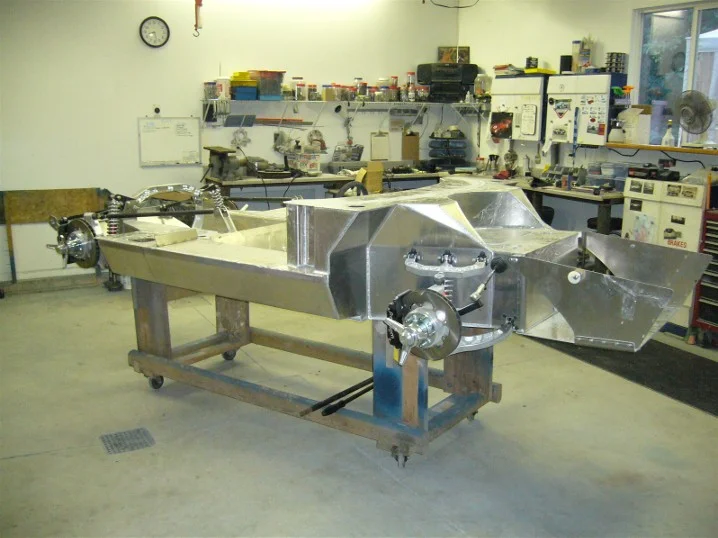
Truck bed liner applied, and ready for the next step.
Additionally, if you would like to surface finish (powder coat, electro plate, polish etc.) the suspension
components, this is the time to do it. All the steel parts are shipped coated with a black primer. It is strongly suggested that at least these components be surface treated (paint, powder coat, electroplate etc.) to prevent corrosion prior to assembly.
Chassis Re-Assembly
Loc-Tite® Red should be used on all fasteners and appropriate bolt torques for each size fastener should be utilized. Here is a handy chart to assist with the torques for specific size fasteners: Torque Chart
Depending on purpose (track / street) you may want to set your suspension up more specific to your need, but these are some good all around numbers for multi purpose application.
|
Initial Alignment Settings |
||
|
LF |
RF |
|
|
- 1/32 |
Toe |
- 1/32 |
|
-0.90 to -1.00 |
Camber |
-0.90 to -1.00 |
|
+ 2.5 to + 5.00 |
Caster |
+ 2.5 to + 5.00 |
|
LR |
RR |
|
|
- 1/32 |
Toe |
- 1/32 |
|
-0.90 to -1.00 |
Camber |
-0.90 to -1.00 |
|
+ 5.00 to + 8.00 |
Caster |
+ 5.00 to + 8.00 |
Before you get started, its not a bad idea to go around the chassis and debur the sharp edges. You will likely be grateful you did later on.
Front Assembly
Note; this will be initial set up and may change when you do your actual alignment. Start by measuring all your control arm spacers and sorting them by thickness. This will make the assembly go easier.
Starting with the forward lower control arm mounting pock, insert one control arm bolt far enough in so that you can hang five spacers and one safety washer as shown the below right picture.
Set lower Heim joints at approximately 1/2 thread exposed. You essentially want these as long as they can safely be, while still having appropriate thread engagement. This will facilitate achieving Negative Camber easier during alignment.
Set control arm in place and install second safety washer and the appropriate combination of different thickness spacers to provide a snug fit into the pocket. Perform the same spacer fitment task on the second mount. The positioning of the lower control arm fore/aft in the mounting pockets is one of the two adjustments for Caster setting (the second being fore/aft adjustments to the upper control arm, which will be covered in subsequent steps). This adjustment is achieved by moving shims from one side to the other of the Heim joint. Once you have desired positioning, torque bolts to spec. Shown washer stacking is a good place to start. You should have the control arm skewed toward front of car. This will help achieve Positive Caster easier.
Rear
Front
For initial set up, be certain to target like positioning on both sides of the chassis.
Now install your upper brackets and torque to spec. Then install shock assembly.
Spacer and washer assembly is identical to the lower control arm. 1) Measure your spacer thicknesses. 2) Start bolt on one side. 3) Hang spacers and washer. 4) Hang shock assy. 5) Insert safety washer and balance of spacers to provide snug fit. 6) Loc-Tite® and torque to spec.
With the shock assemblies hung, you can now install the upper control arm. Install the upper ball joint, threaded as far in as possible. This is important for alignment purposes to achieve Negative Camber. Loc-Tite® and torque the ball joint.
Once again, the shim stack and safety washer installation process is identical to the lower arm. The only difference is you want to skew the control arm toward the rear this time. This should provide an initial Positive Caster position to start your alignment from.
You can now install the uprights. When doing so, don't forget to index the cotter pin holes so installation of the pins will be easier (i.e. facing fore/aft, not toward the upright). Note, there should be a washer under the ball joint nuts to avoid galling of the aluminum. Do not tighten nut down directly against the aluminum upright.
Before you install the front bearing assemblies, it is suggested that you coat the interface with either a silicone or graphite anti-seize. Once again, Loc-Tite® the threads and torque to spec all fasteners.
Rear Assembly
Once again, layout all your spacers by thickness. Install the rear trailing rods in the same manner as the front assemblies. Loc-Tite® and torque to spec.
Note: The rear links are different lengths. The longer rods must be installed in the upper positions.
Note: If you are installing a +2 suspension, you must use "High Angle" Heim joints in the forward positions.
With the trailing rods in place, you can now install the lower control arm. Much like with the front, make the lower control arm heim joints "long". If you have a +2 suspension, you will need to test fit to max length, as the lower trailing rods may contact the outboard side of the chassis if the lower control arm heim joints are too long.
The lower control arm installation also encompasses the installation of the rear pan and short link brackets.
Install upper tubular control arms to a nominal length setting.
Also be concious of the clearance between the tubular upper control arm and the bolt heads on the rear horseshoe. It will be necessary to add three washers
Install shock assembly as shown. Be conscious of safety washer order and direction.
Install rear pan link bars. Now that the rear assemblies are hung. The rear bearings should be Loc-Tite'd® and torqued to spec (130Nm (96 lb-ft).
If using U-joint style drive shafts, the Corvette stub axles should be clearanced for provide higher articulation of the joint. The degree of clearance needed is dependent upon your suspension set up, what shocks will be utilized, long or short control arms, whether suspension limiting straps are being utilized etc. Bottom line; once the drive train is in, you need to check that you have bind free rotation at full rebound. If there is bind, then additional clearancing will be necessary. Make it a point to circle back and confirm on this! The left photo is before, right photo is after.
Before
After
Stub axle shafts should now be installed. This is important, because they hold the bearing together.
Note: Bearing disassembly (or bearing damage) can occur if the car is rolled without the stub shafts installed. The rear axle stub shafts should be tightened to 160 Nm (118 ft/lbs).
Before assembling the knock off hubs, the studs must be shortened by 0.155" (3.94mm). After shortening, the stud should end at the end of the threads inside the drive pin as shown below right.
Nowinstall drive pins, use Loc-Tite® and torque to 75 ft/lbs (101 N/m). Additionally, Loc-Tite® and torque to spec rotor mounts.